A Core Provider is the system that proves a user’s or device’s identity. Creating a core provider in the JoinNow Management Portal tells the Cloud Connector system how to verify user credentials and register the MAC address of the onboarding device.
To create a core provider, perform the following steps:
- Log in to the JoinNow Management Portal.
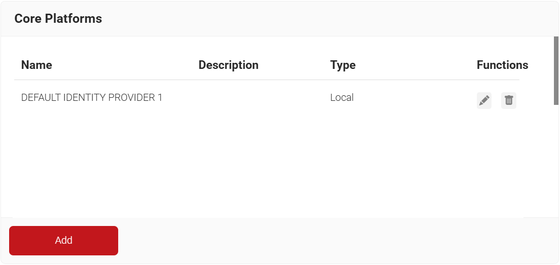
- Navigate to the Integration Hub > Core Platforms.
- Click Add.
- In the Name field, enter the name of the core provider.
- In the Description field, enter a suitable description for the core provider.
- From the Type drop-down list, select Okta SAML.
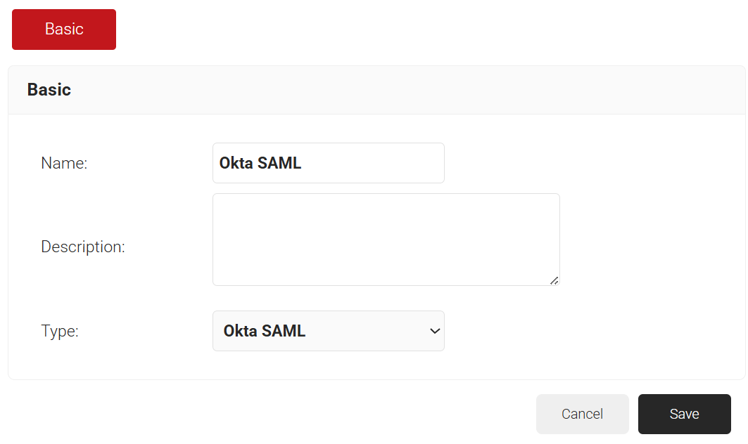
- Click Save.
The RADIUS configurations from JoinNow are configured in Cisco to enable the AAA set-up in the wireless controller.
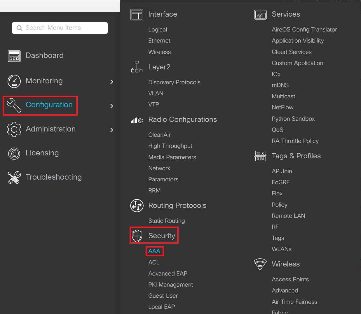
- Log in to the Cisco Catalyst 9800-L Wireless Controller portal.
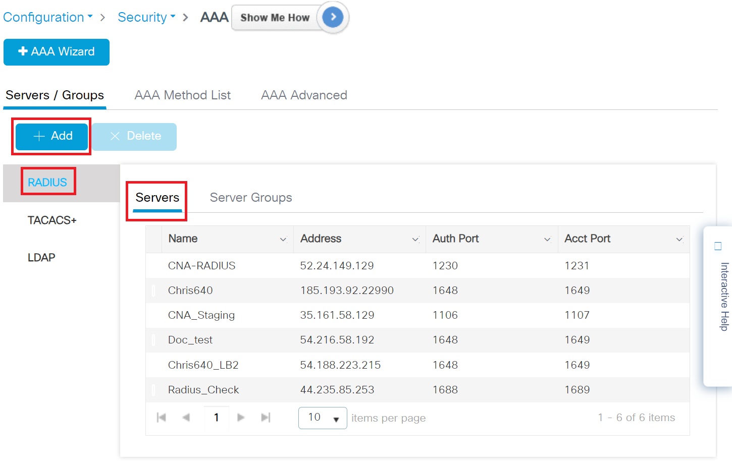
- Navigate to Configuration > Security > AAA.
- Under Servers/Groups, click RADIUS in the Servers tab and then click the +Add button to create a new server.
- On the Create AAA RADIUS Server window, configure the following details:
- In the Name field, enter the name of the RADIUS server.
- To obtain the AAA configuration details from the JoinNow Management Portal, navigate to RADIUS > RADIUS Configuration. Copy the Primary IP Address, Authentication Port, Accounting Port, and Shared Secret values.
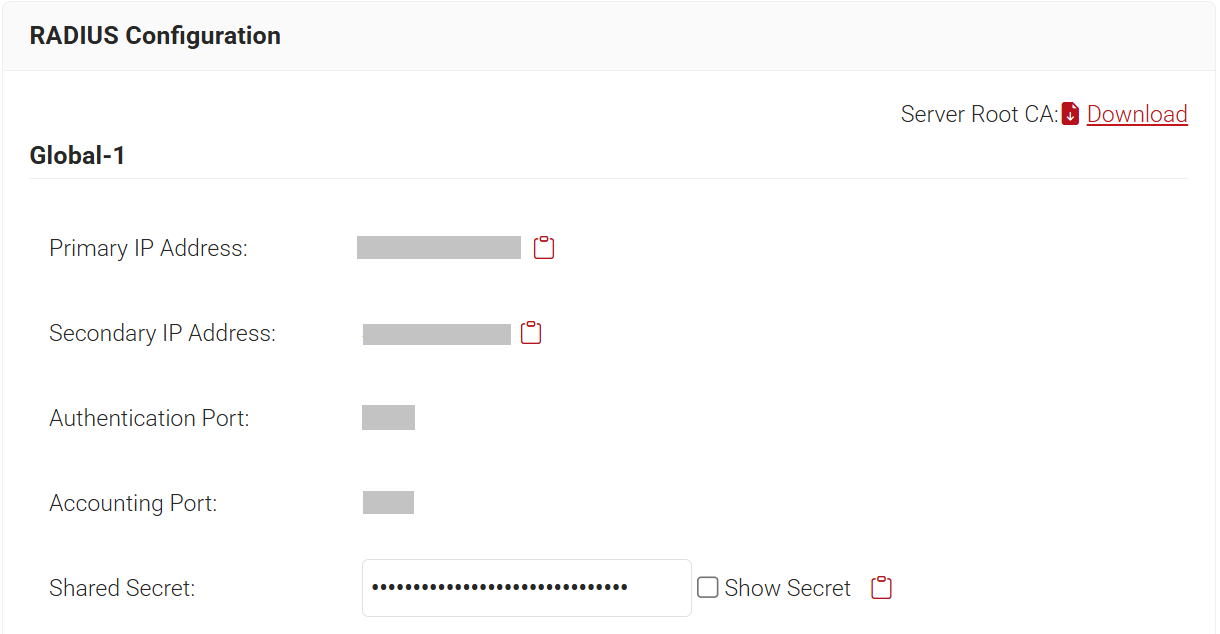
- For the Server Address field, enter the Primary IP Address value obtained from the JoinNow Management Portal.
- For the Auth Port field, enter the Authentication Port value obtained from the JoinNow Management Portal.
- For the Acct Port field, enter the Accounting Port value obtained from the JoinNow Management Portal.
- For the Key and Confirm Key fields, enter the Shared Secret value obtained from the JoinNow Management Portal.
- In the Server Timeout field, enter the duration in seconds.
- In the Retry Count field, enter the desired number of retry attempts.
- Use the Support for CoA toggle button to enable or disable change of authorization (CoA).
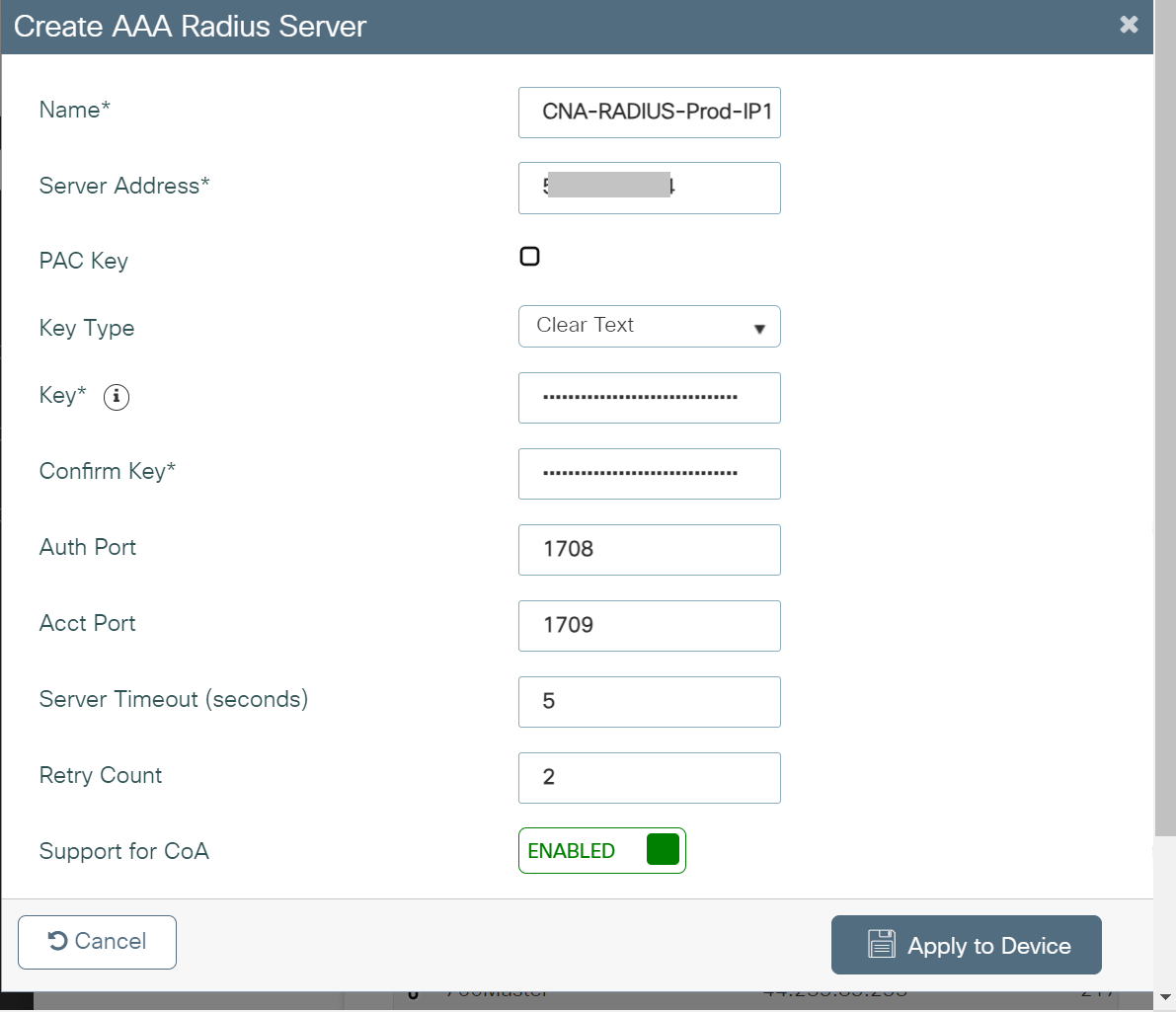
- Click Apply to Device.
To add the server to a server group:
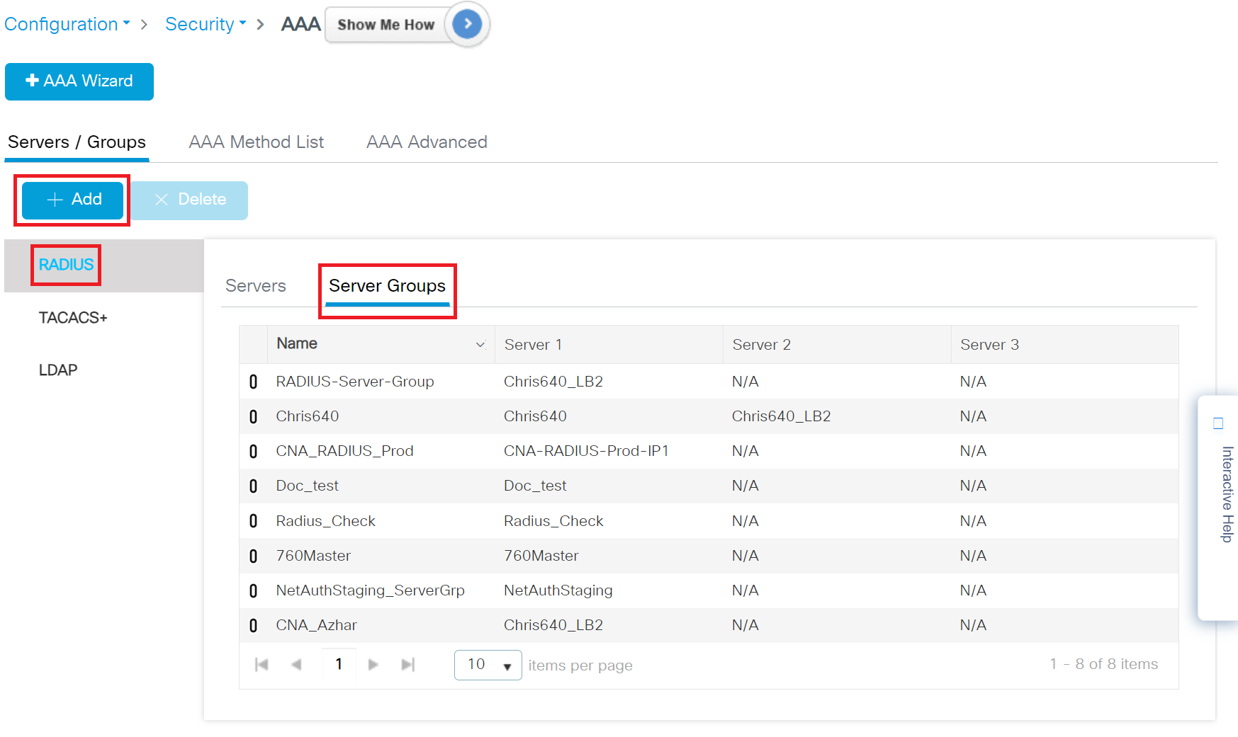
- Navigate to Configuration > Security > AAA.
- Under Servers/Groups, click RADIUS in the Server Groups tab and then click the +Add button to create a new server group.
- On the Create AAA RADIUS Server pop-up window, configure the following details:
- In the Name field, enter the name of the server group.
- From the Available Servers list, add the server created in the Adding a RADIUS Server in Cisco section to the Assigned Servers list.
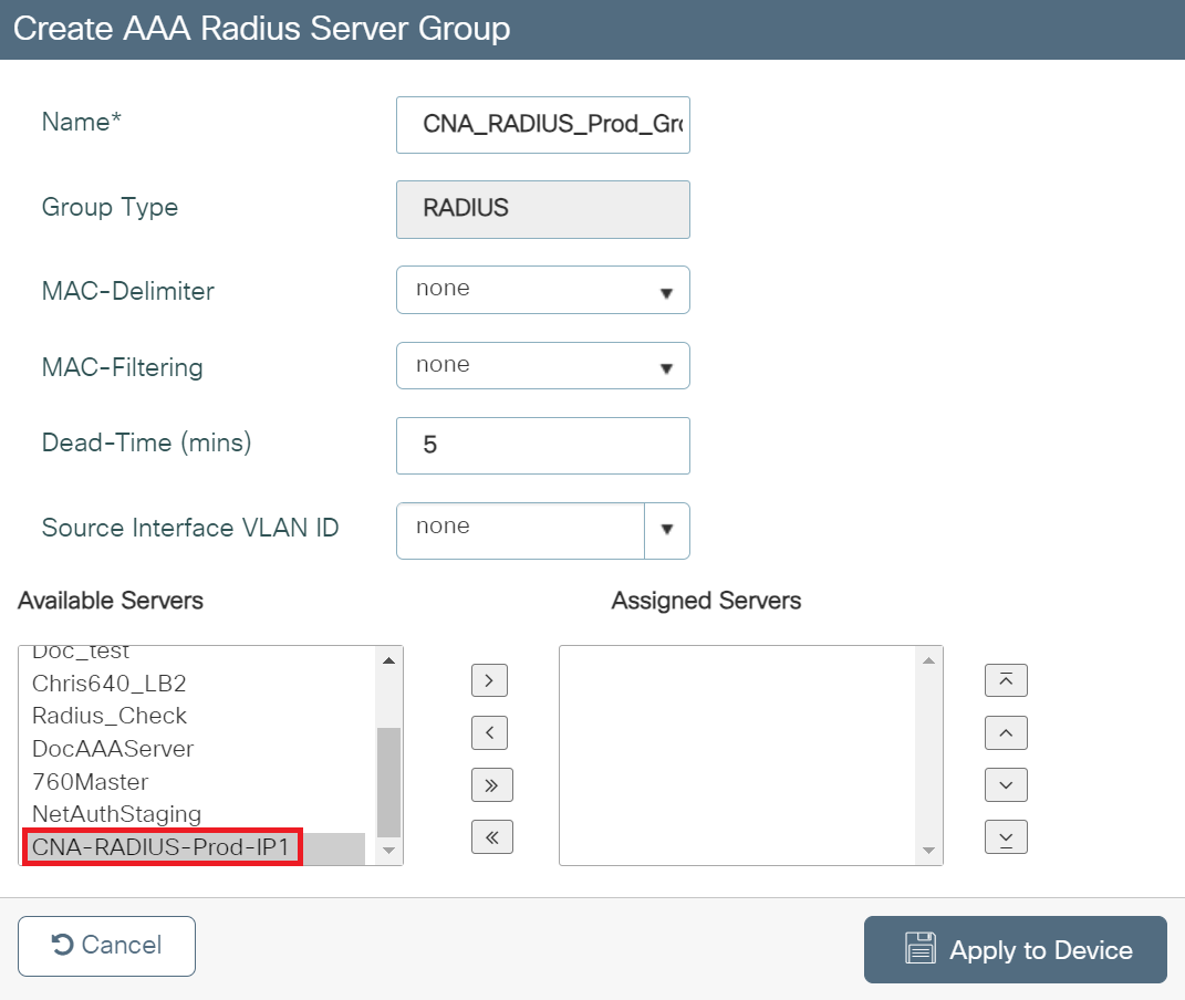
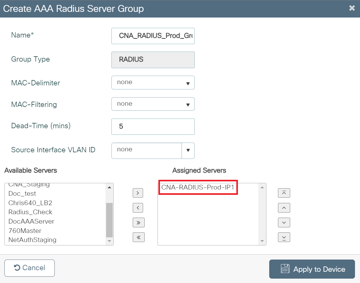
- Click Apply to Device.
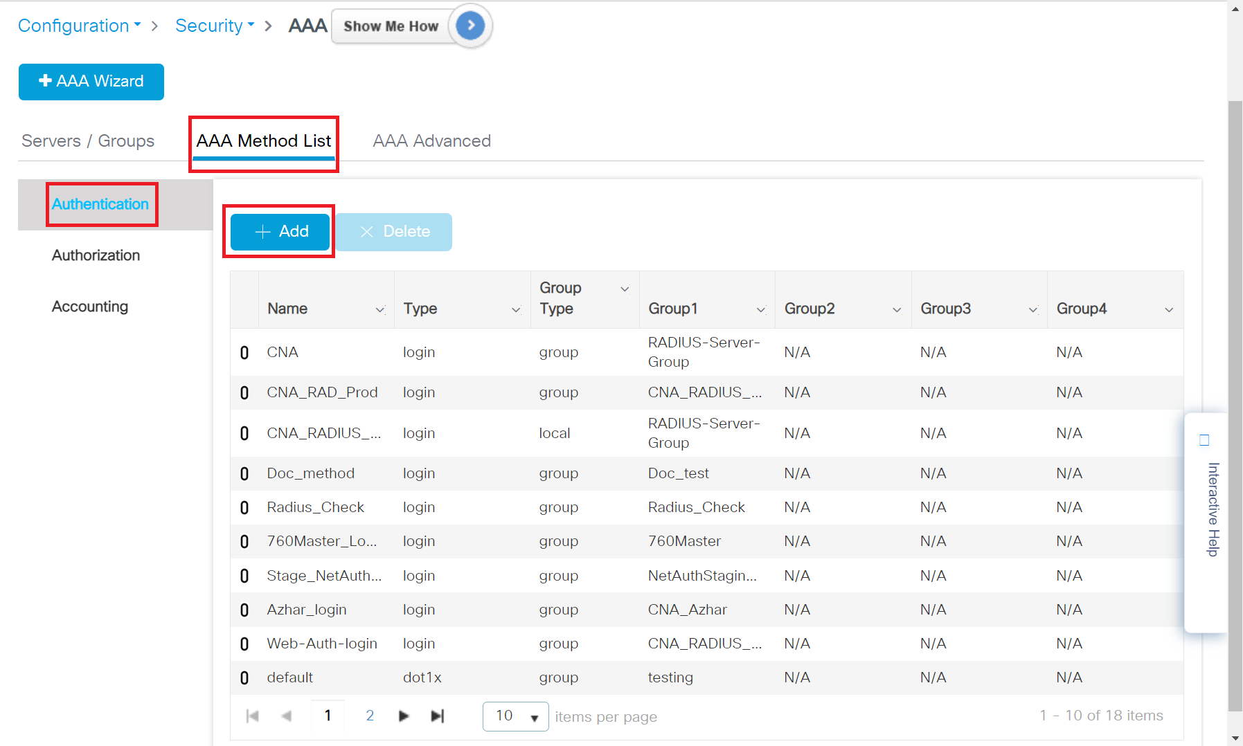
To create an AAA method list for Login, perform the following steps:
- Navigate to Configuration > Security > AAA.
- Under the AAA Method List tab, click Authentication and then click + Add.

- In the Method List Name field, enter a name for your AAA Authentication.
- From the Type drop-down, select login.
- From the Available Server Groups list, add the server group created in the Adding RADIUS Server to a Server Group section to the Assigned Server Groups list.
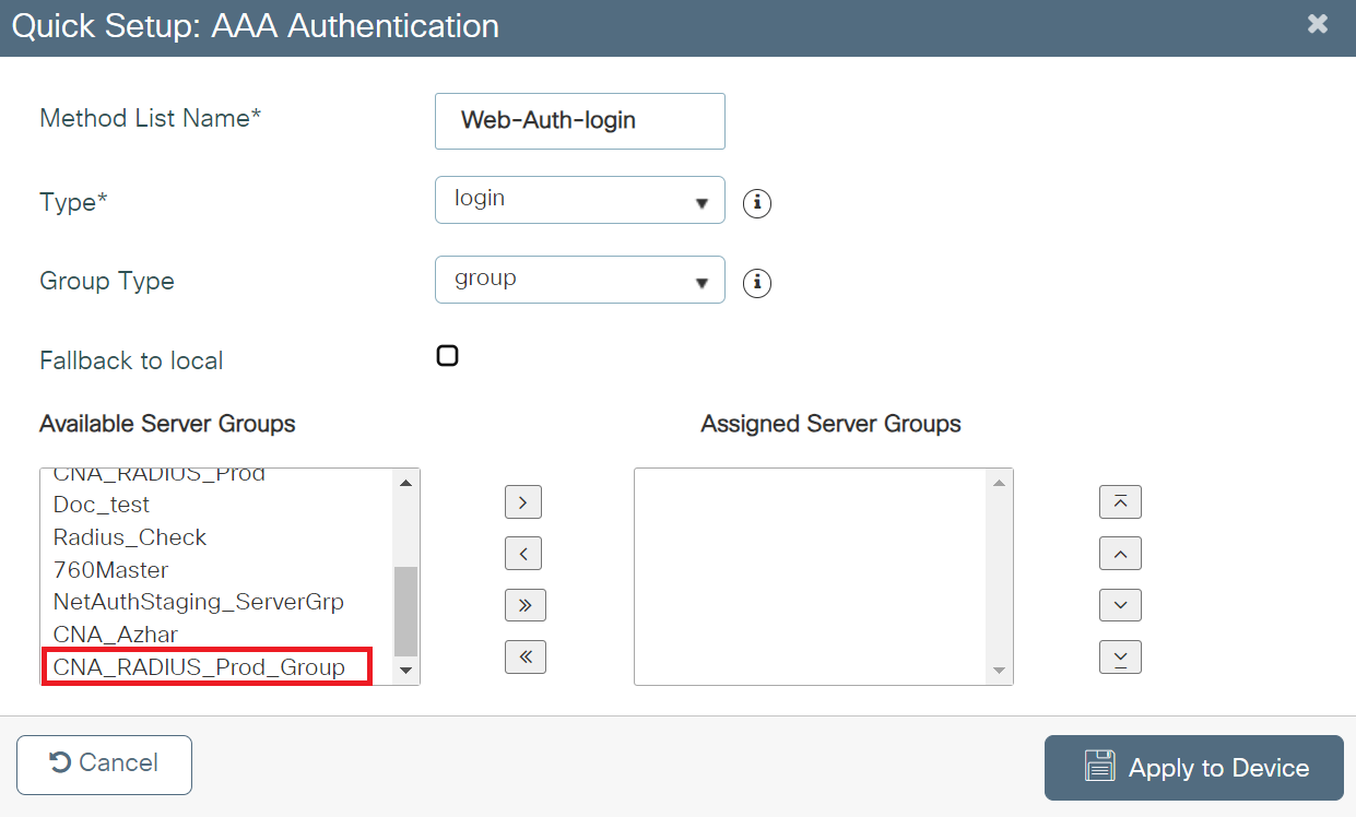
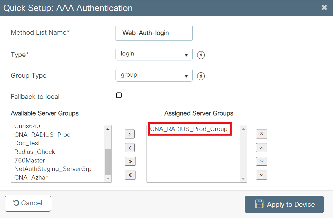
- Click Apply to Device.
To create an AAA method list for dot1x, perform the following steps:
- Navigate to Configuration > Security > AAA.
- Under the AAA Method List tab, click Authentication and then click + Add.
- In the Method List Name field, enter a name for your AAA Authentication.
- From the Type drop-down, select dot1x.
- From the Available Server Groups list, add the server group created in Adding RADIUS Server to a Server Group to Assigned Server Groups list.
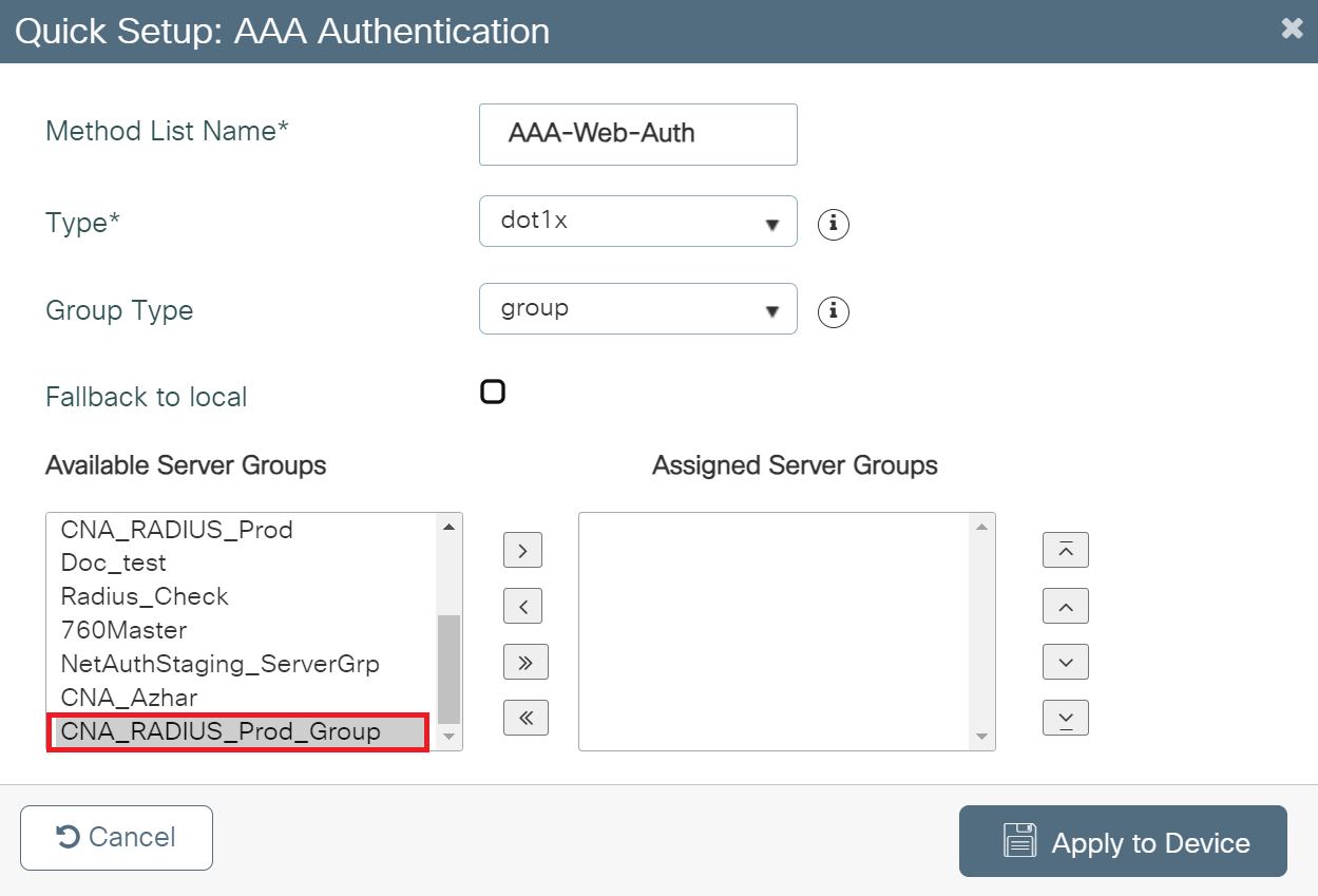
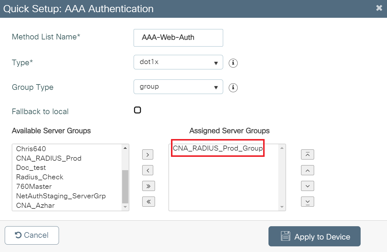
- Click Apply to Device.
The Web Auth parameter is configured with the redirect URL, which will lead the customers to the landing page.
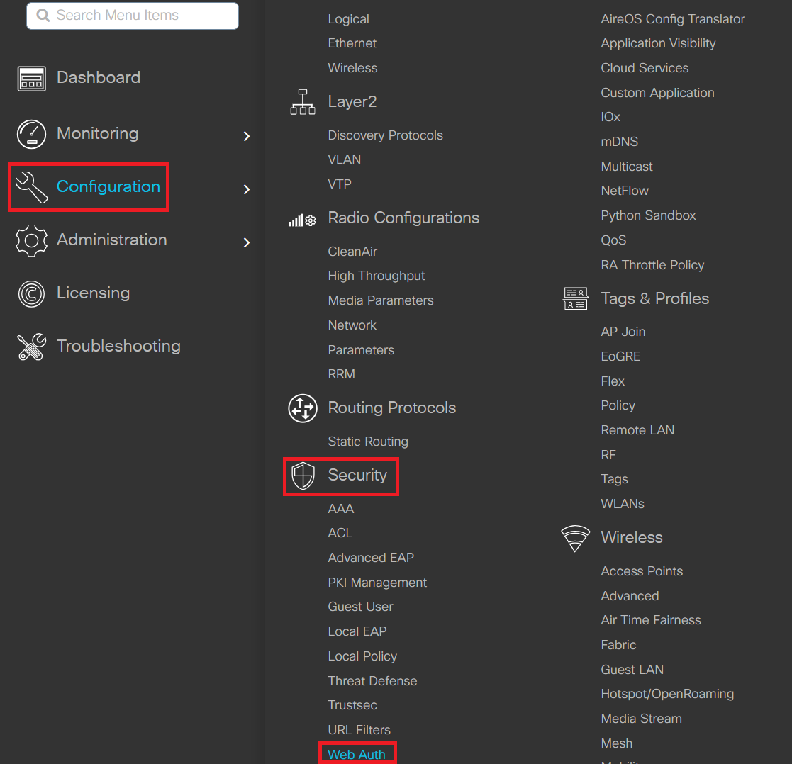
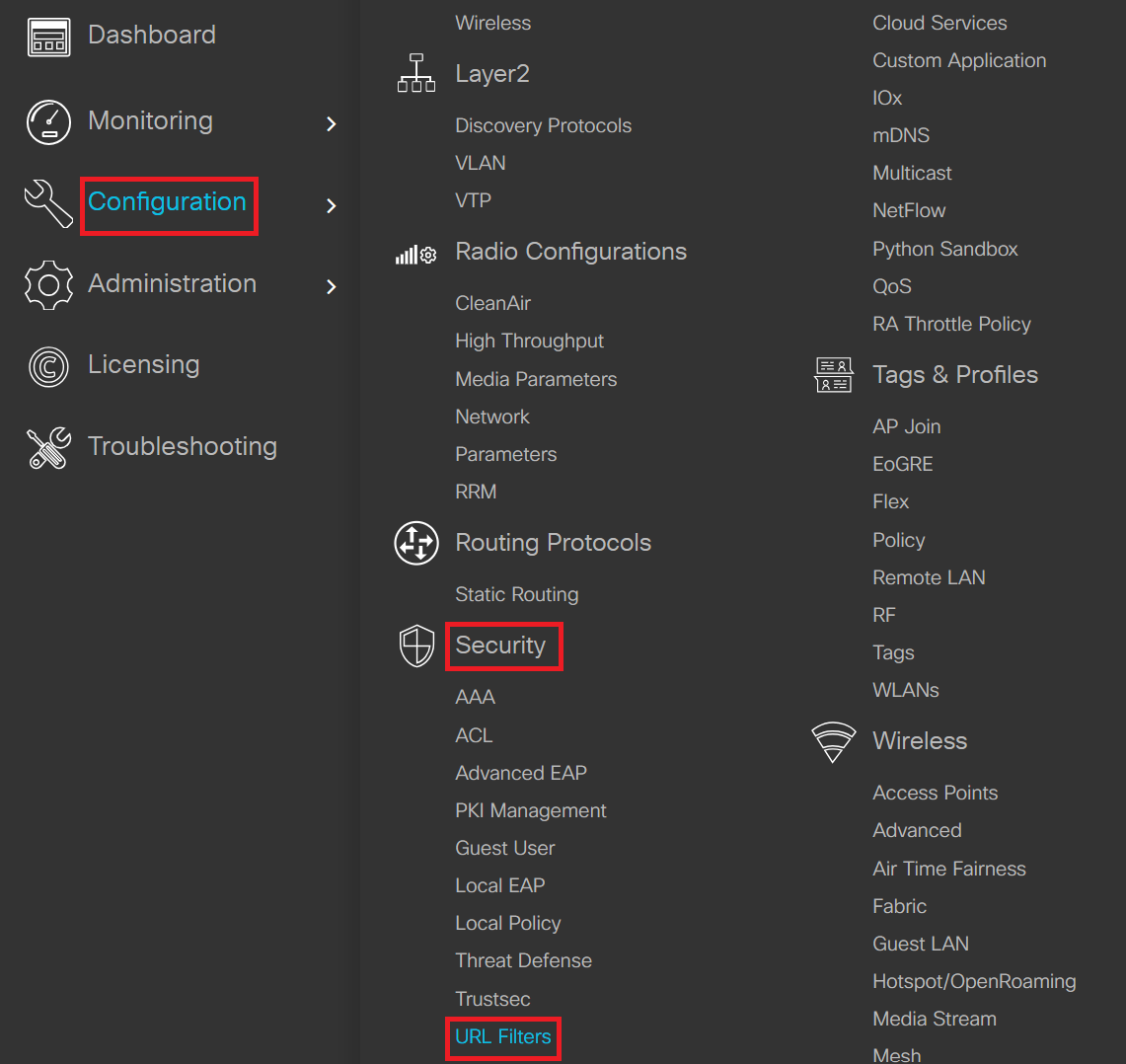
- Navigate to Configuration > Security > Web Auth.
- Click + Add to create a new Web Auth Parameter.
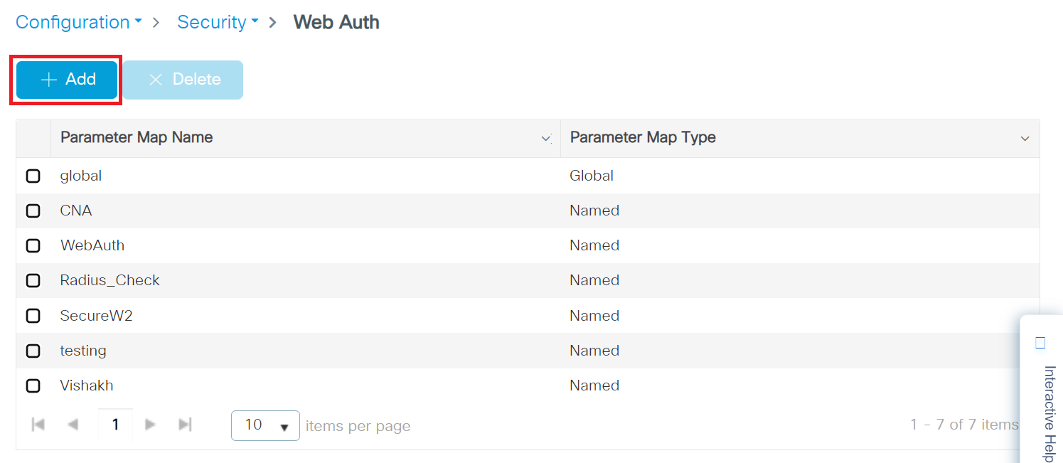
- In the Create Web Auth Parameter pop-up window, enter a name for the parameter map in the Parameter-map name field.
- In the Maximum HTTP connections field, enter the maximum number of HTTP connections you want to allow. The valid range is 1-200.
- In the Init-State Timeout field, enter the duration after which the init-state timer should expire if the user fails to enter valid credentials on the login page. The range is 60-3932100 seconds.
- In the Type drop-down list, select the Webauth option that appears during the login process.
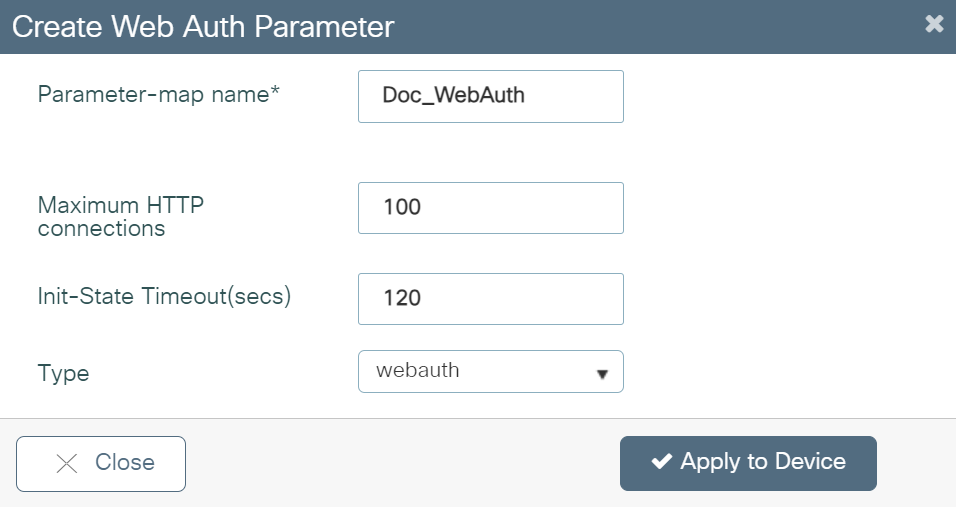
- Click Apply to Device. The newly created parameter map appears in the list of parameter maps on the Web Auth page.
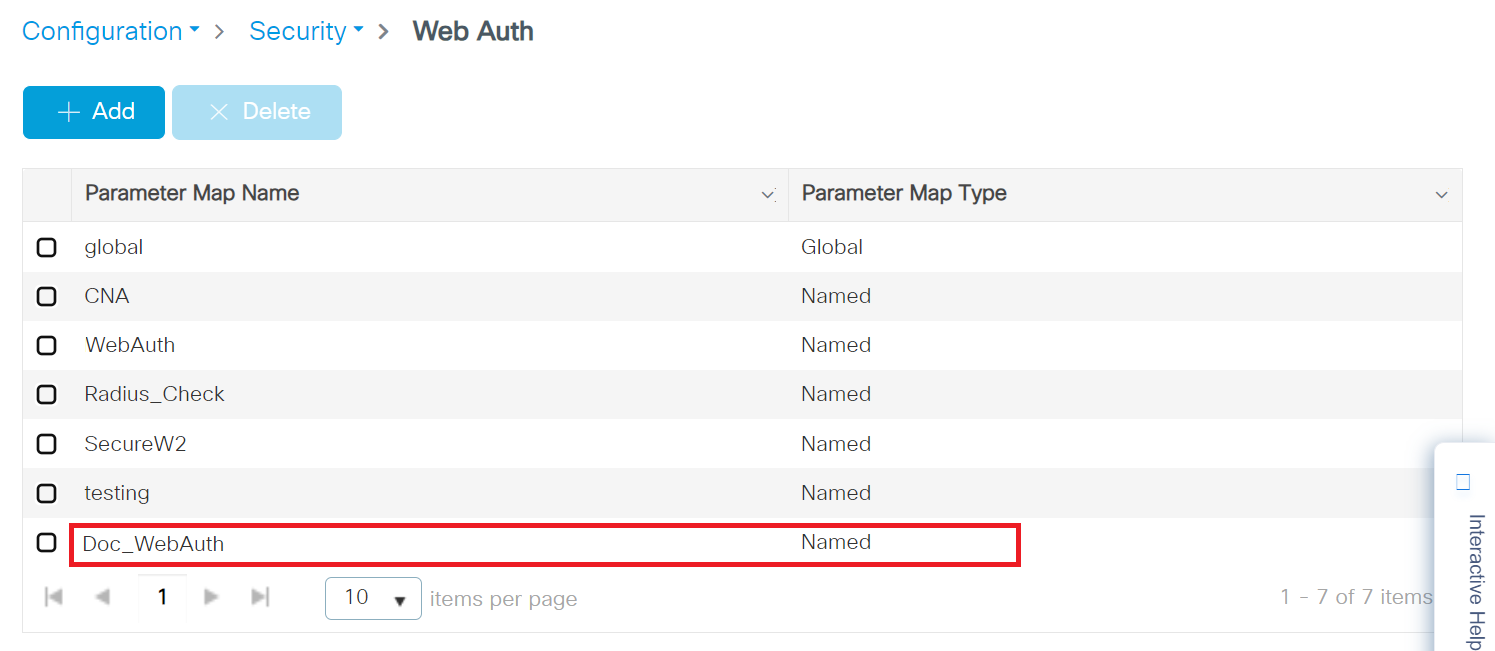
- On the Web Auth page, click the name of the parameter map that you created earlier (refer to step 2).
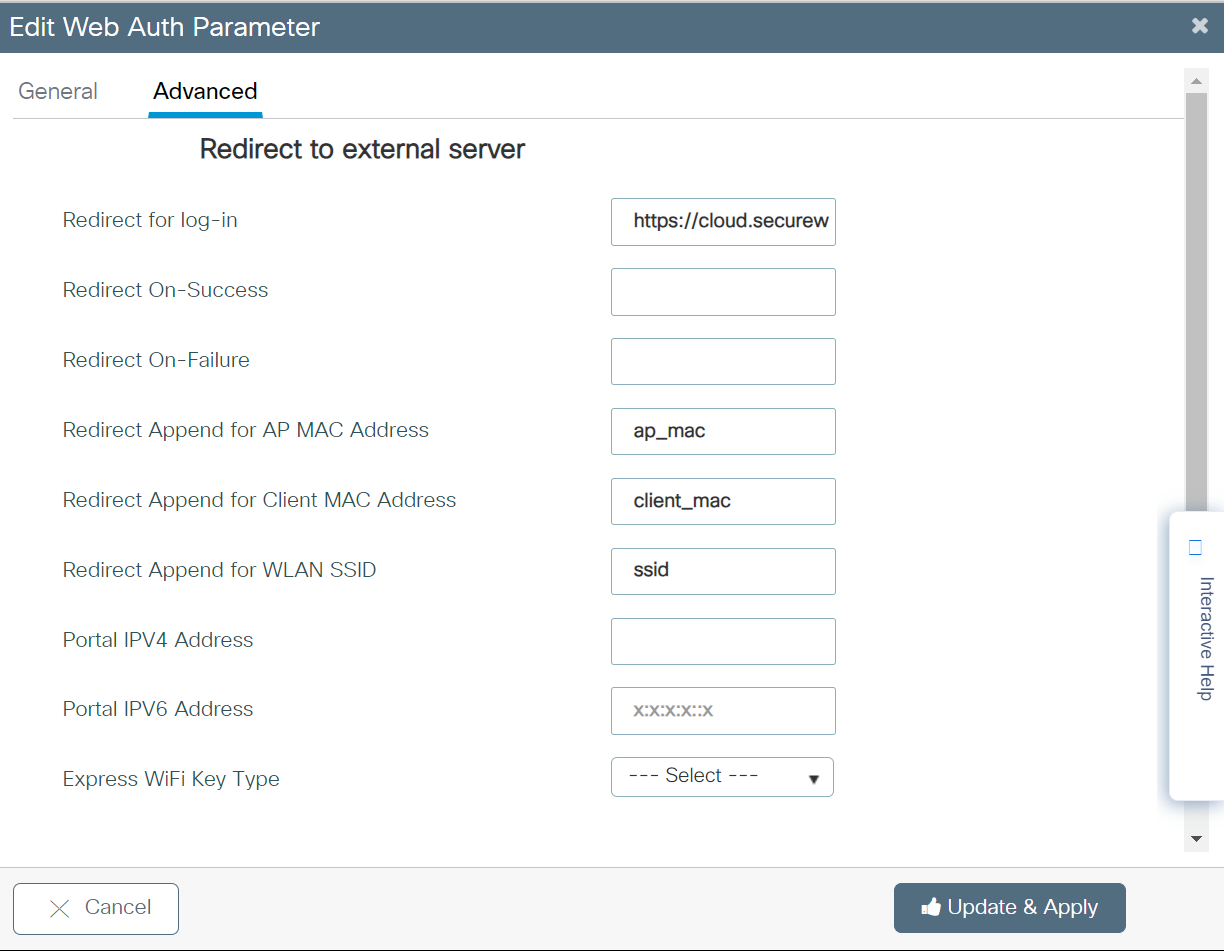
- In the Edit Web Auth Parameter pop-up window that appears, navigate to the Advanced tab.
- Under the Redirect to external server section, in the Redirect URL for log-in field, enter the URL with which the user will be routed to the Landing page.
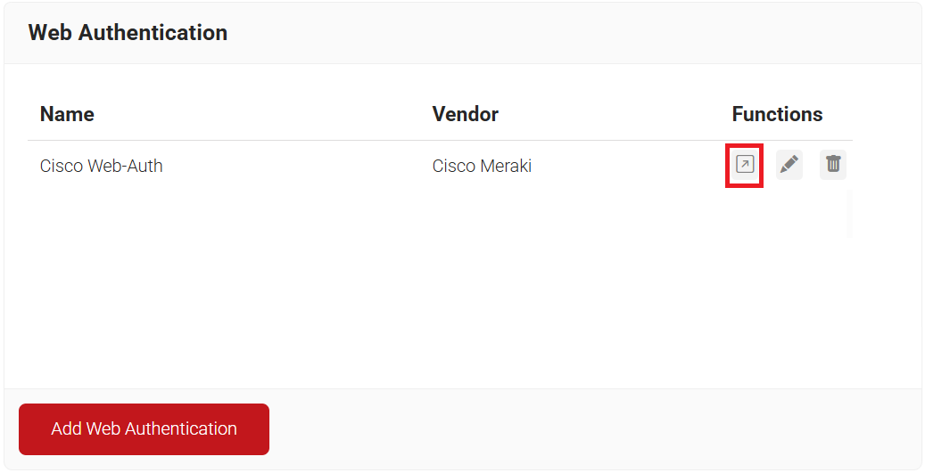
To create the Landing URL, perform the following steps:- Log in to the JoinNow Management Portal.
- Navigate to Device Onboarding > Web Authentication.
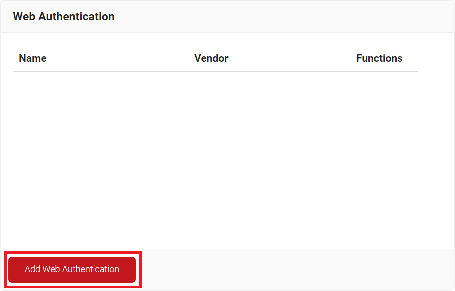
- In the Basic section, enter the name of the Web Authentication in the Name field.
- In the Display Description field, enter a suitable description for the Web Authentication.
- From the Vendor drop-down list, select Cisco Meraki.
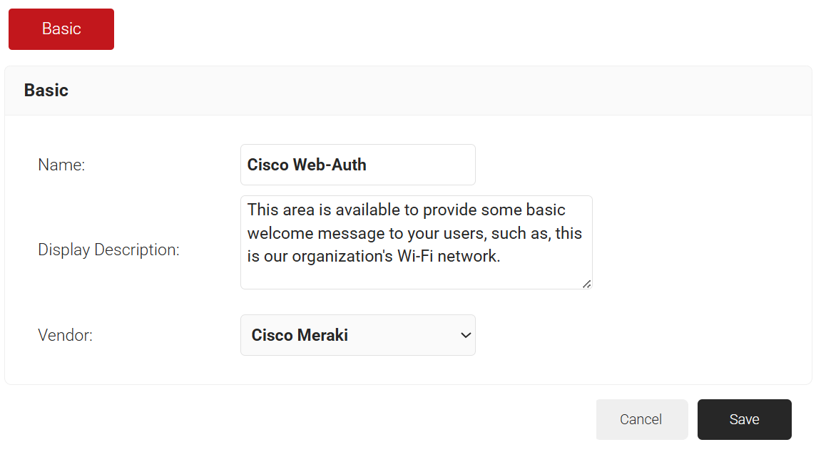
- Click Save.
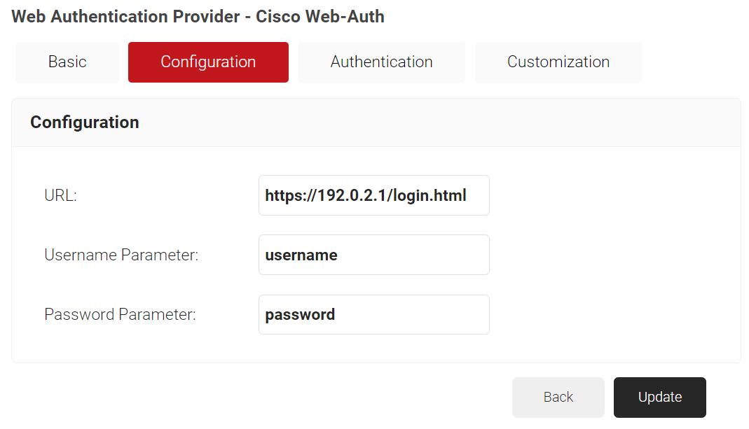
- Click the Configuration tab.
- In the URL field, enter https://192.0.2.1/login.html. This redirect URL is specific to Cisco.
- Click the Authentication tab.
- In the Authentication section, from the Core Provider drop-down list, select the core provider created earlier in the Creating a CoreProvider section.
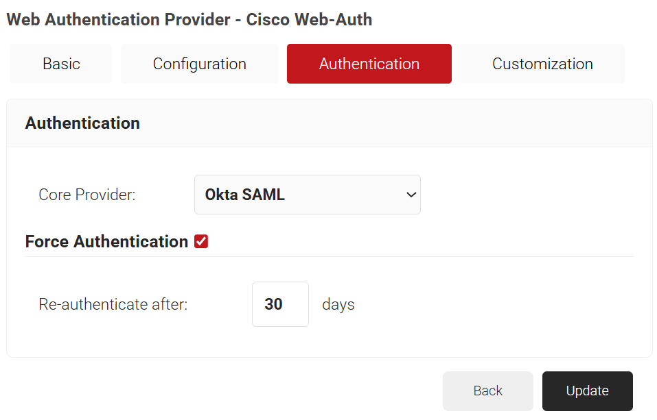
- Click Update.
- On the Web Authentication page, click the Open landing page icon and copy the landing page URL.
- In the Redirect Append for AP MAC Address field, enter the variable – ap_mac
- In the Redirect Append for Client MAC Address field, enter the variable – client_mac
- In the Redirect Append for WLAN SSID field, enter the variable – ssid
- Click Update & Apply.
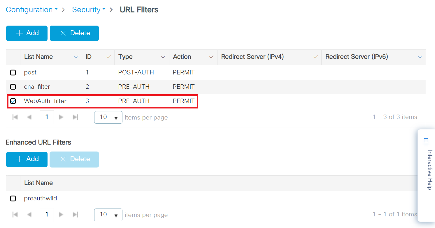
To configure the URL Filter List, perform the following steps:
- Navigate to Configuration > Security > URL Filters.
- On the URL Filters page, click the + Add button.
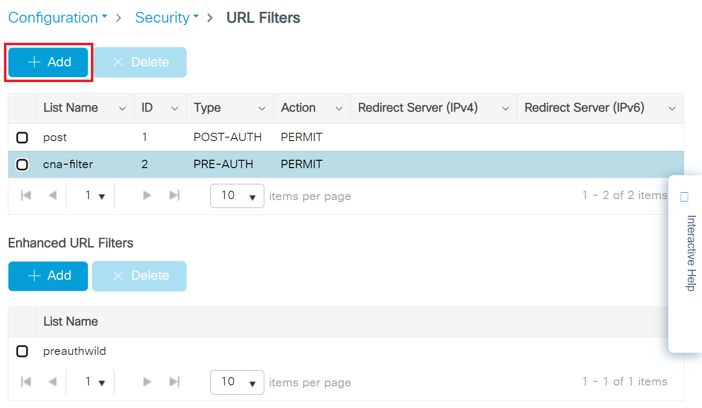
- On the Add URL Filters pop-up window, configure the following details:
- In the List Name field, enter a name for the URL filter list.
- From the Type drop-down list, select PRE-AUTH.
- In the Action field, enable the PERMIT button.
- In the URLs field, enter the ACL to allow the URLs.
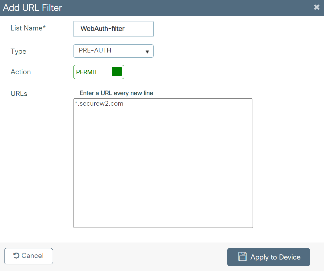
- Click Apply to Device.
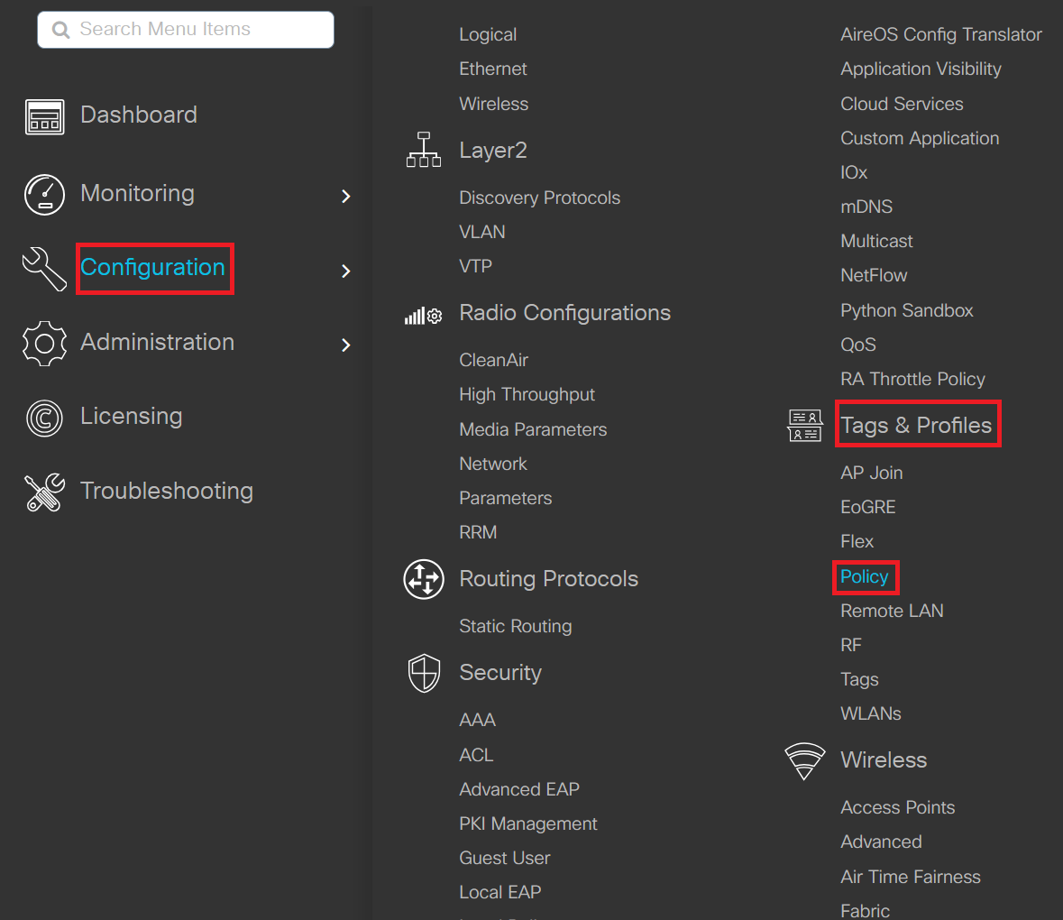
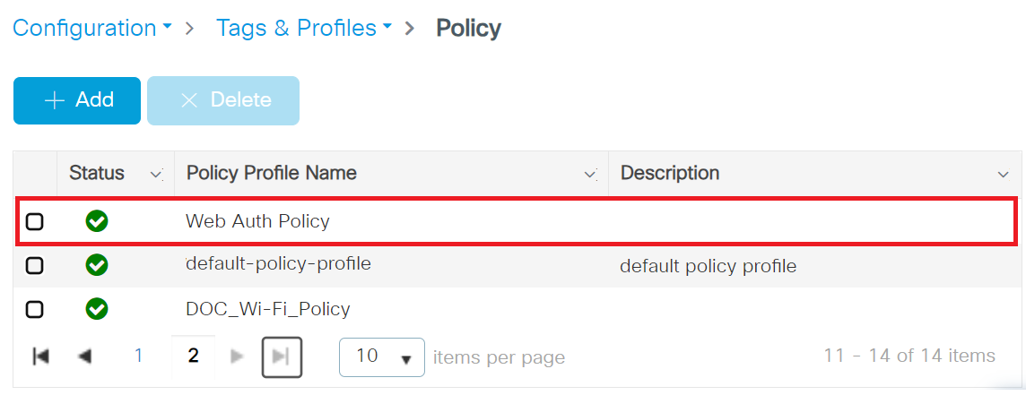
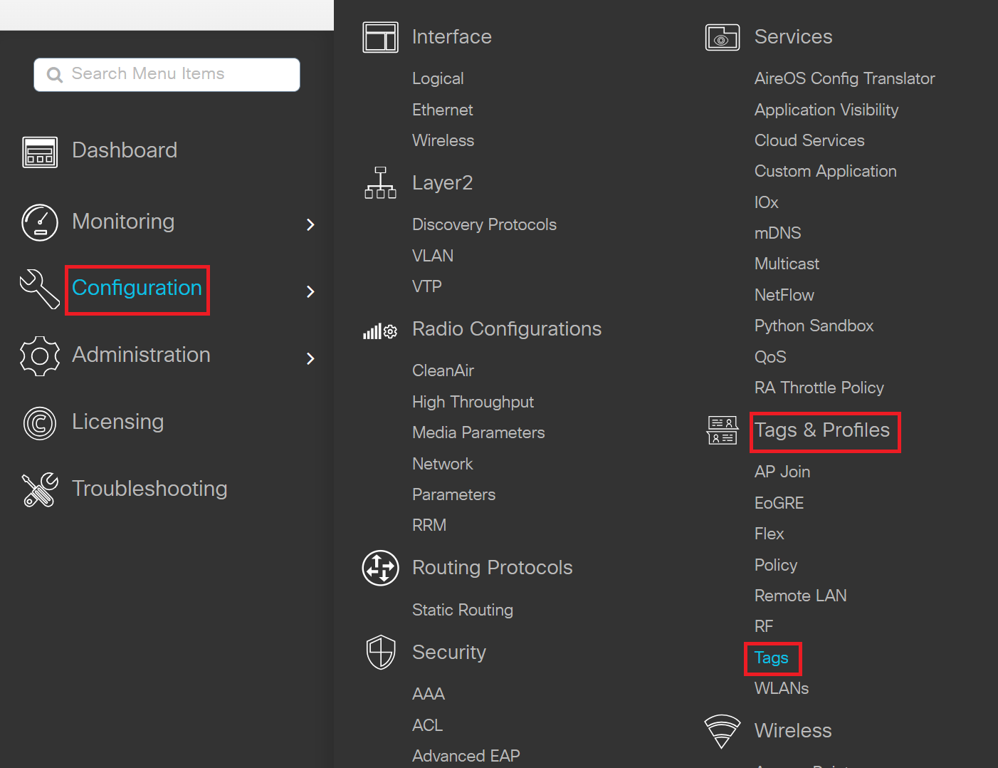
- Navigate to Configuration > Tags & Profiles > Policy.
- On the Policy page, click + Add.
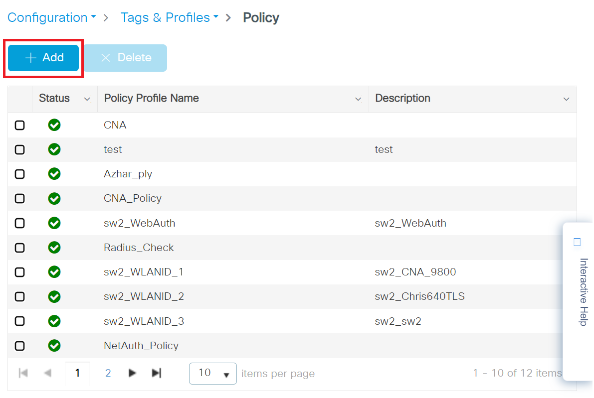
- On the Add Policy Profile window, under the General tab, enter a name for the policy profile in the Name field.
- Toggle the Status button to ENABLED state.
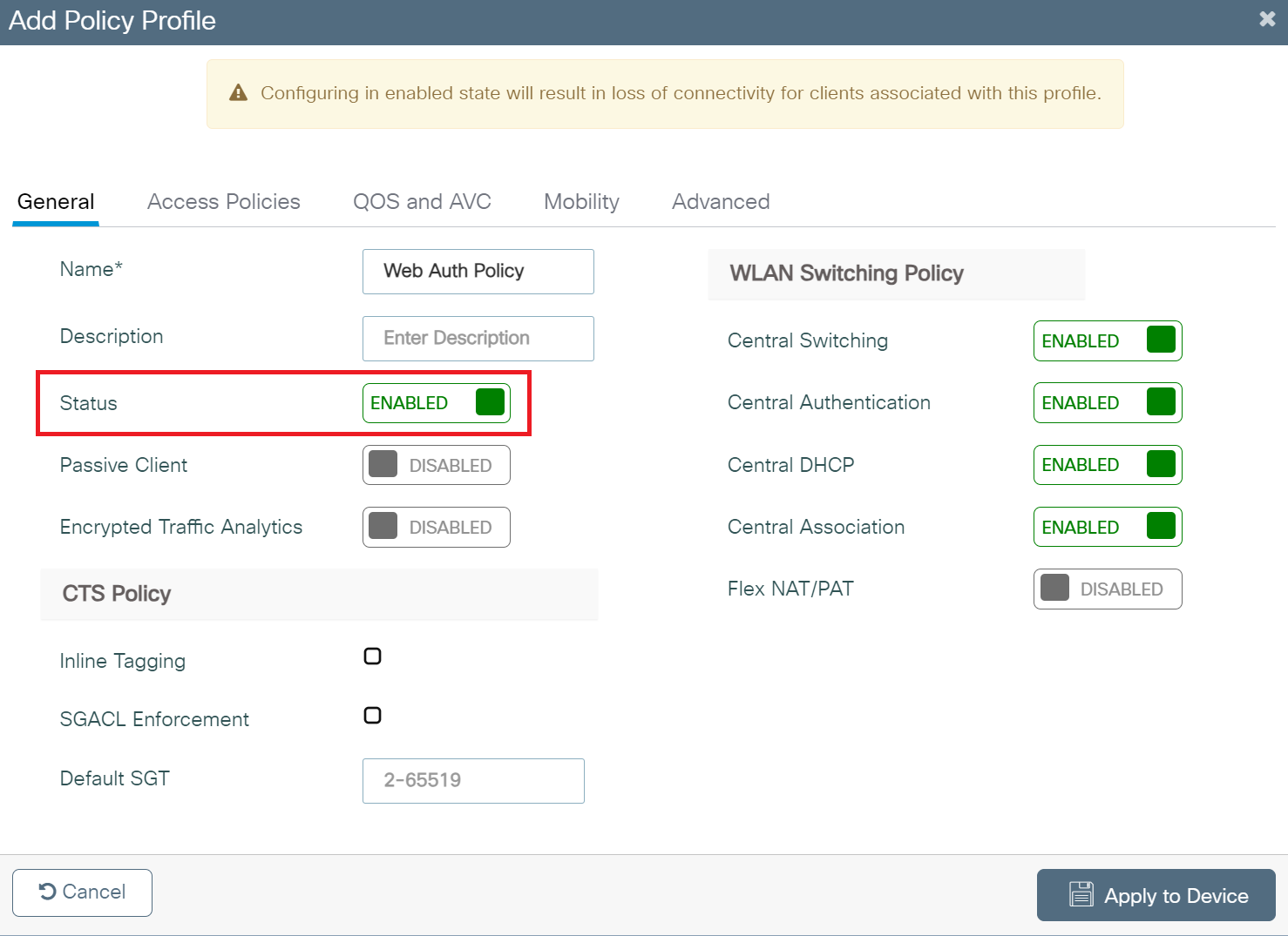
- Click the Access Policies tab and configure the following details:
- In the URL Filters section, from the Pre Auth drop-down list, select the Pre-Auth url filter created in the Configuring the URL Filter List section.
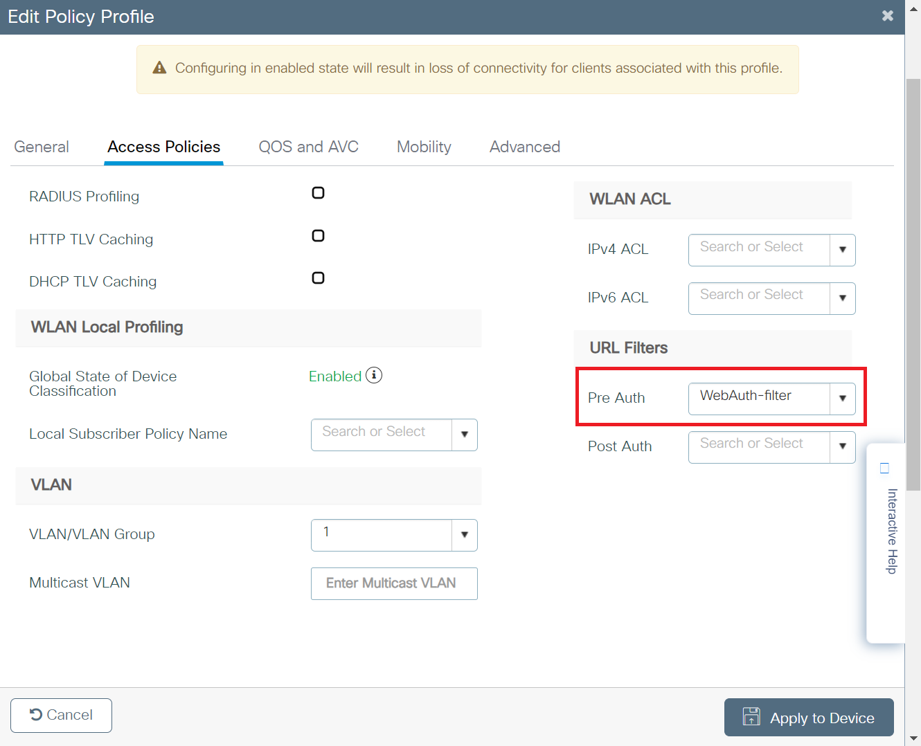
- In the URL Filters section, from the Pre Auth drop-down list, select the Pre-Auth url filter created in the Configuring the URL Filter List section.
- Click Apply to Device.
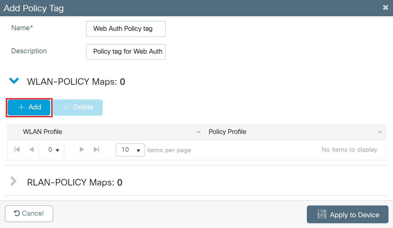
- Navigate to Configuration > Tags & Profiles > Tags.
- In the Policy Tags page, click + Add.
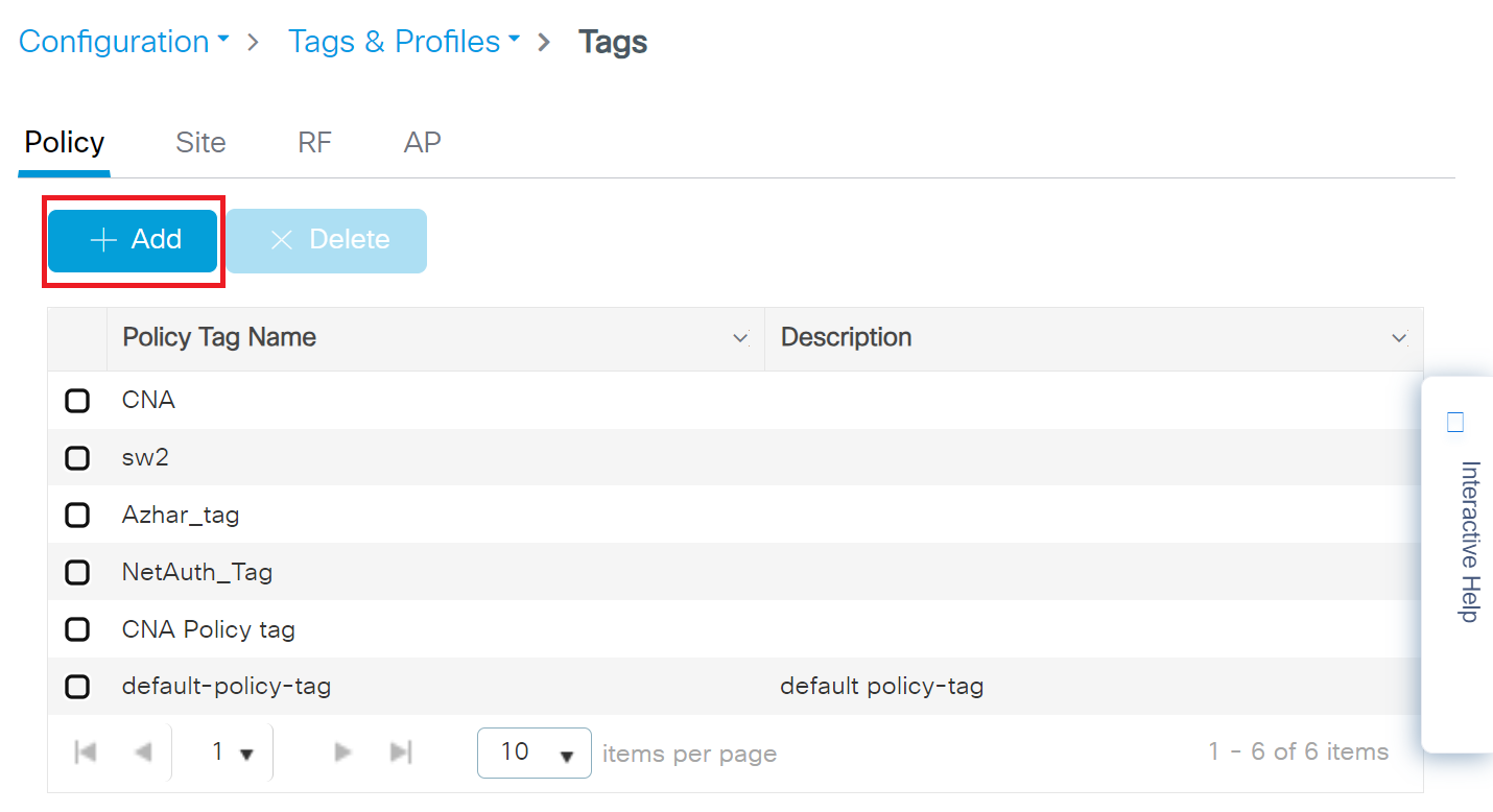
- On the Add Policy Tag pop-up window, in the Name field, enter a name for the policy tag.
- Expand WLAN-POLICY Maps and click + Add.
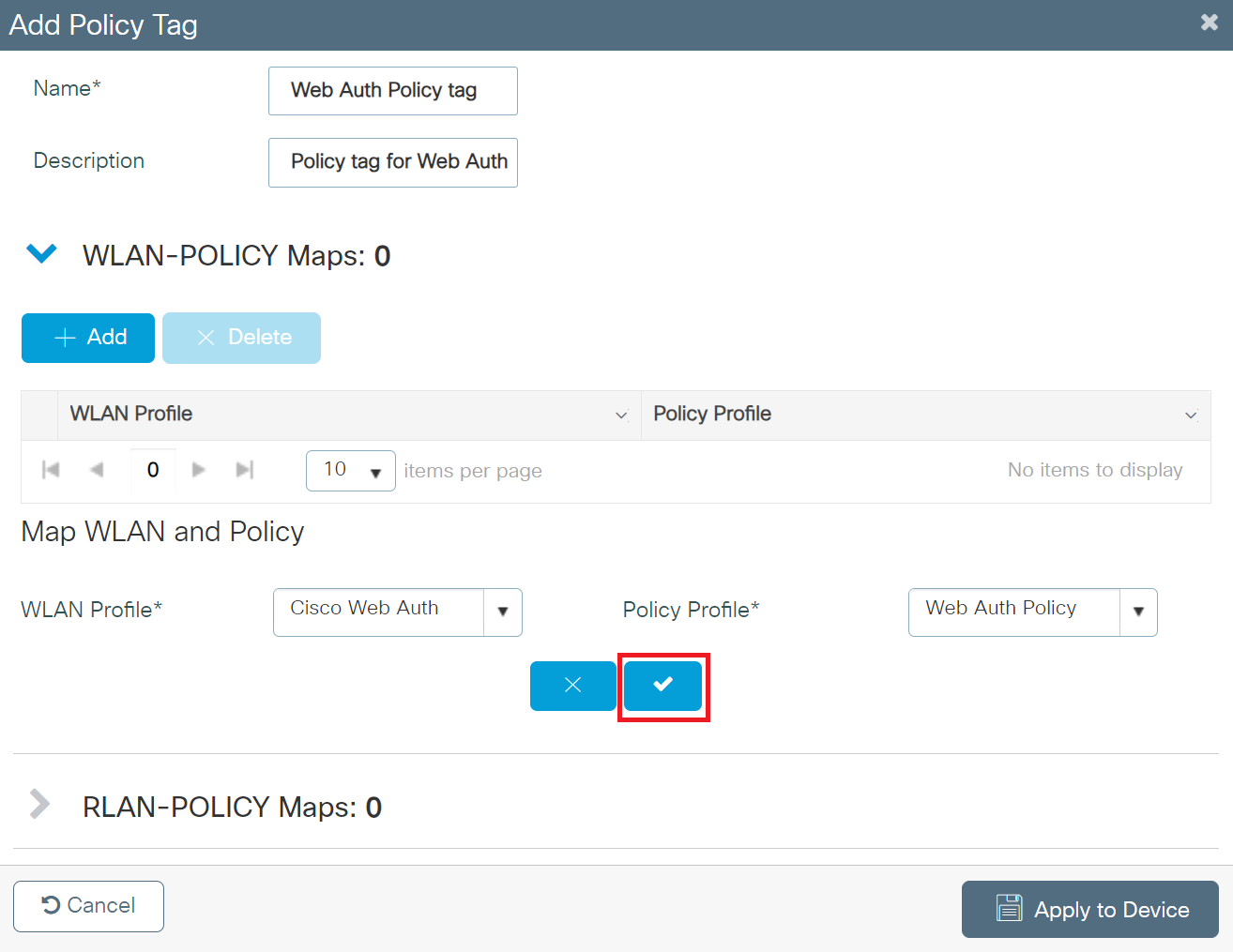
- From the WLAN Profile drop-down list, select the SSID profile created in the Configuring the Broadcasting SSID section.
- From the Policy Profile drop-down list, select the policy created in the Creating a Policy Profile section.
- Click the button with a tick mark to save the WLAN and Policy profiles.
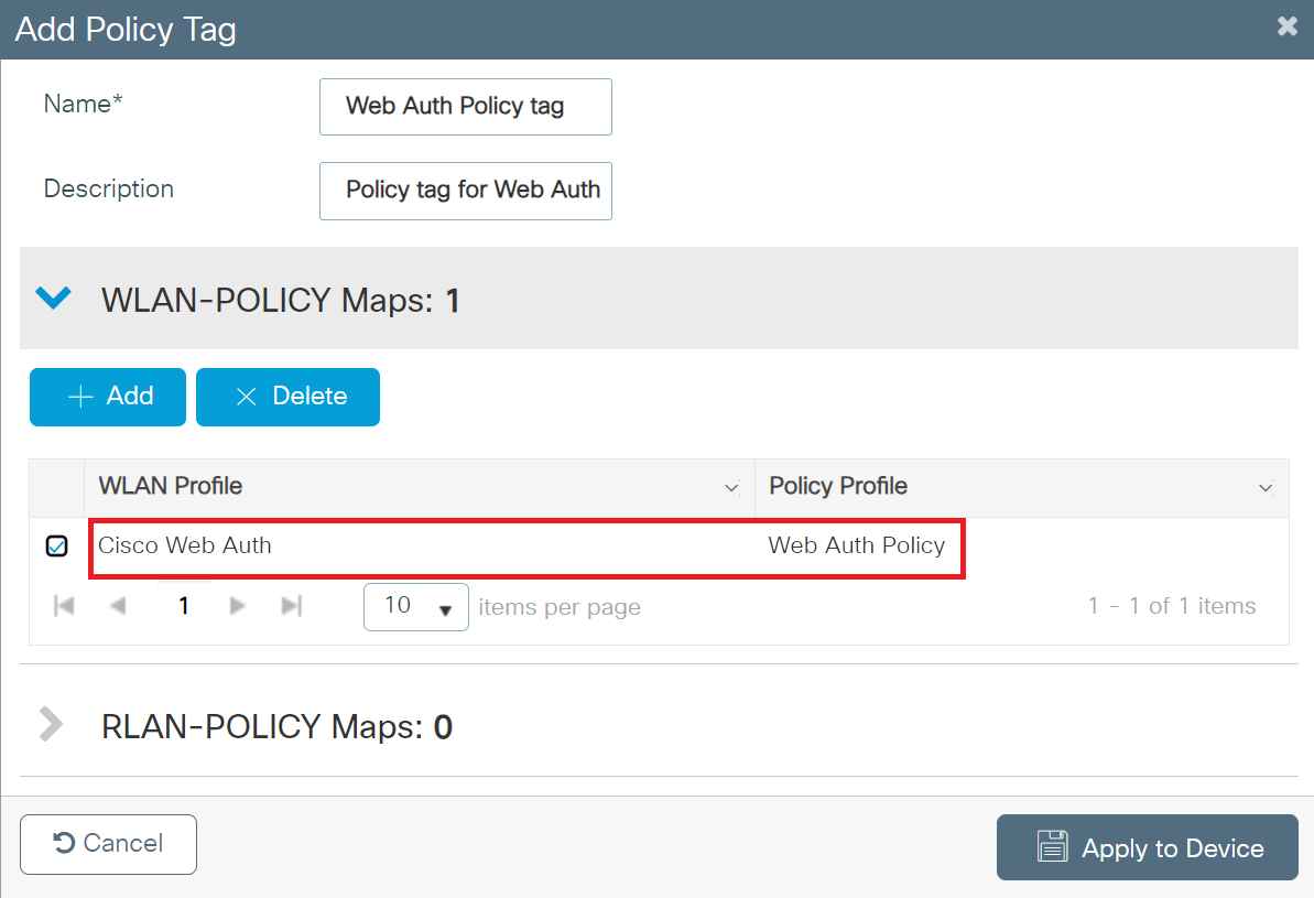
- Click Apply to Device.
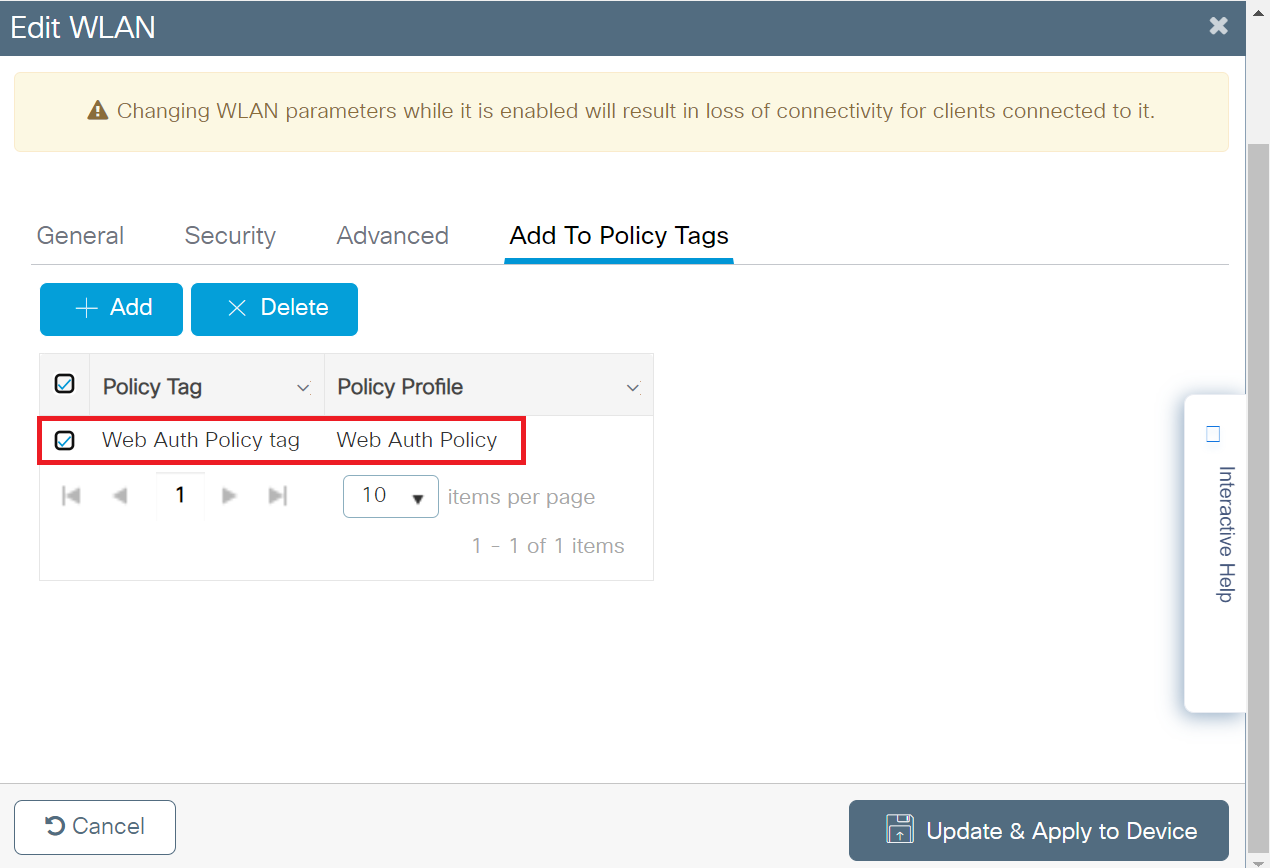
- To view the assigned Policy tag, perform the following steps:
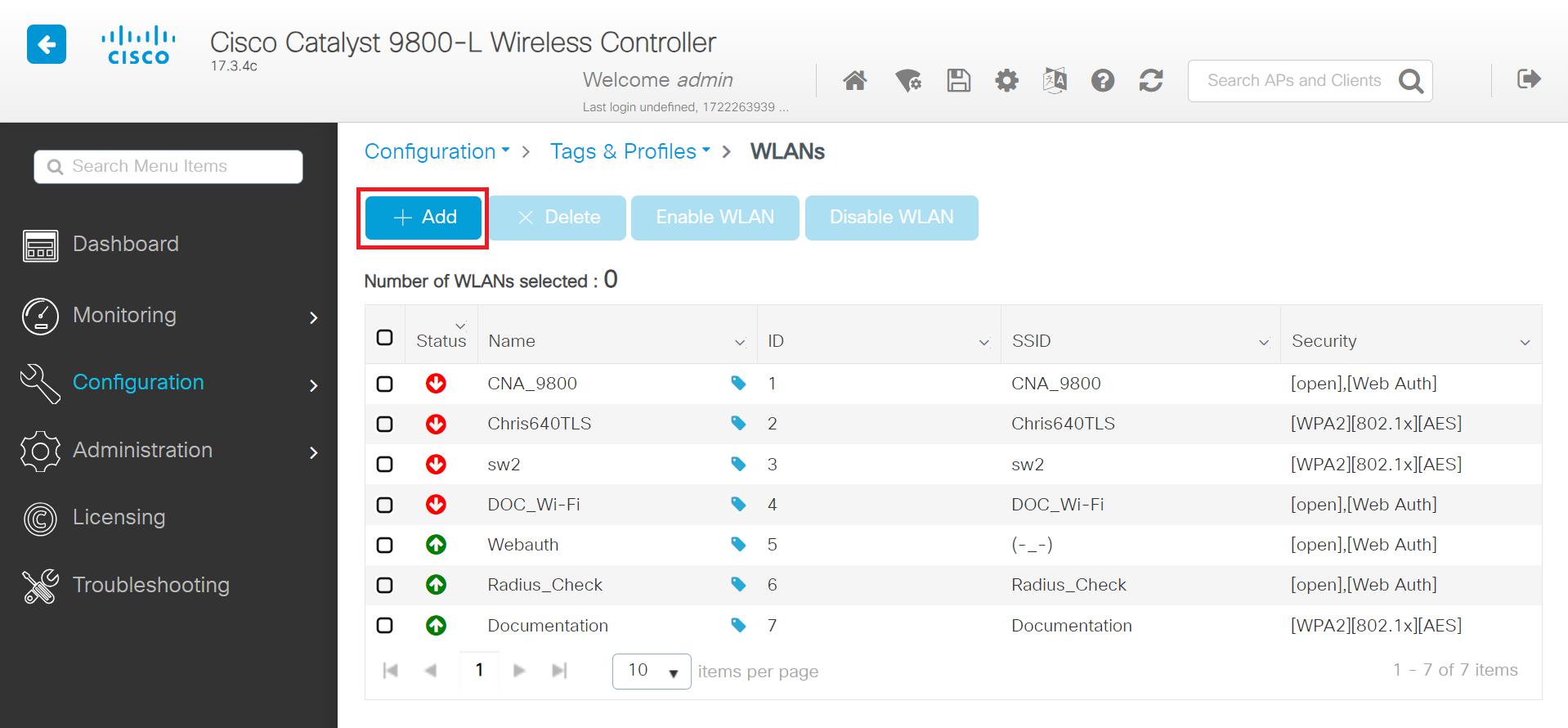
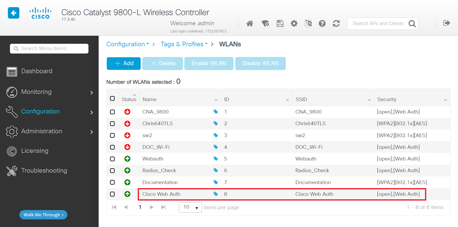
- Navigate to Configuration > Tags & Profiles > WLANs.
- Click the WLAN profile created earlier in the Configuring the Broadcasting SSID section.
- Click the Add To Policy Tags tab. The Policy Tags are assigned to the WLAN profile, as shown in the screenshot below.
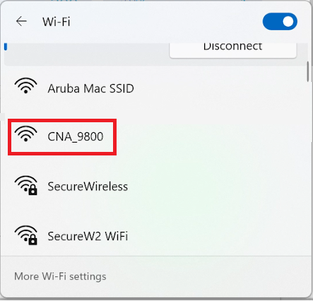
The broadcasting SSID is the open network that the device connects to before being authenticated into the secure network.
To create a WLAN, perform the following steps:
- Navigate to Configuration > Tags & Profiles > WLANs.
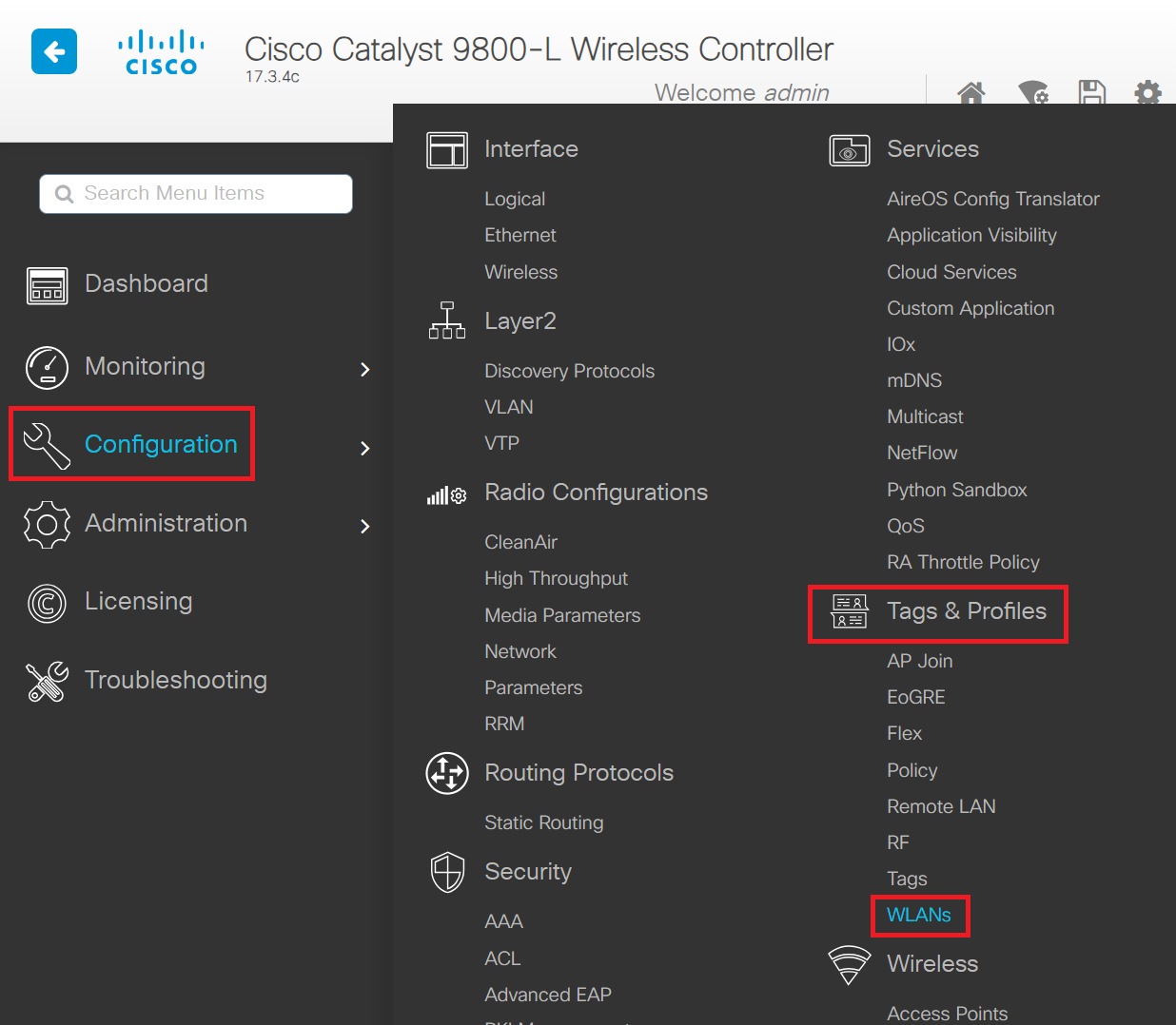
- Click + Add to create a new WLAN Profile.
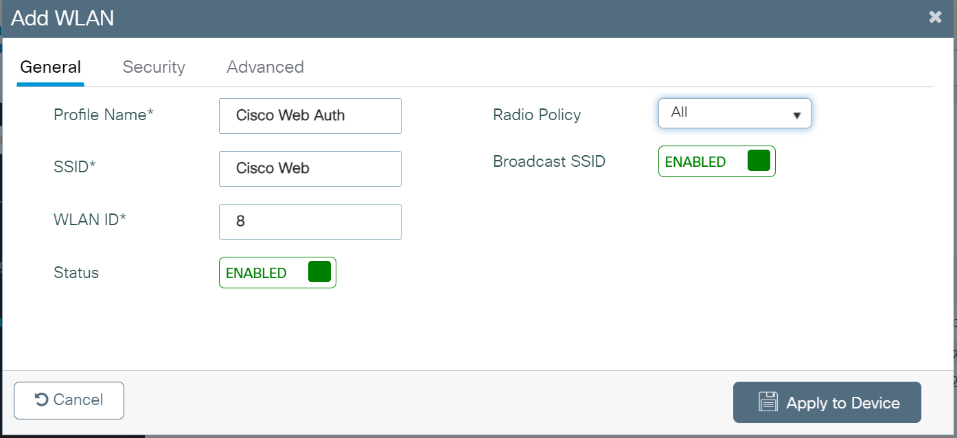
- On the Add WLAN pop-up window, in the General tab, enter the profile name in the Profile Name field.
- In the SSID field, enter the SSID name. By default, the profile name entered in the previous step is automatically used as the SSID. You can either use this default name or enter a new one.
- In the WLAN ID field, enter a valid ID between 1 and 4096. This field is automatically populated by the system with an available ID. You may assign a new ID if needed.
- Toggle the Status button to ENABLED state.
- If the Broadcast SSID is disabled, click the toggle button to enable the SSID broadcast, making it visible to all wireless clients within range.
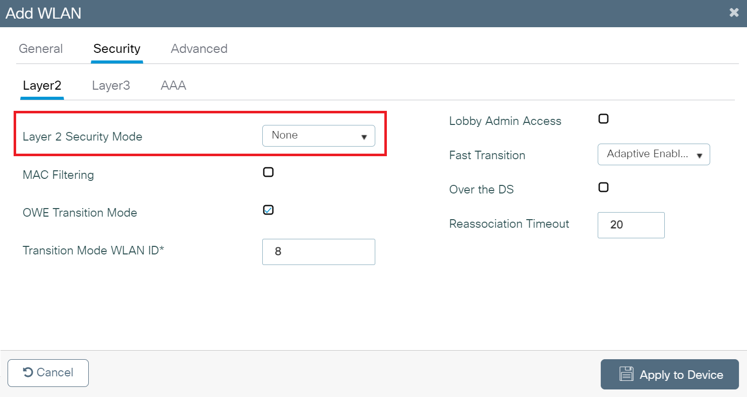
- Go to the Security tab, then under the Layer2 tab, in the Layer 2 Security Mode drop-down list, choose None. For web authentication, disable all Layer 2 security features.
- Under the Layer3 tab, select the Web Policy checkbox.
- From the Web Auth Parameter Map drop-down list, select the parameter map you created earlier in the Creating the WebAuth Parameter section.
- From the Authentication List drop-down list, select the authentication list you created in the Creating a Login Type AAA Method List section.
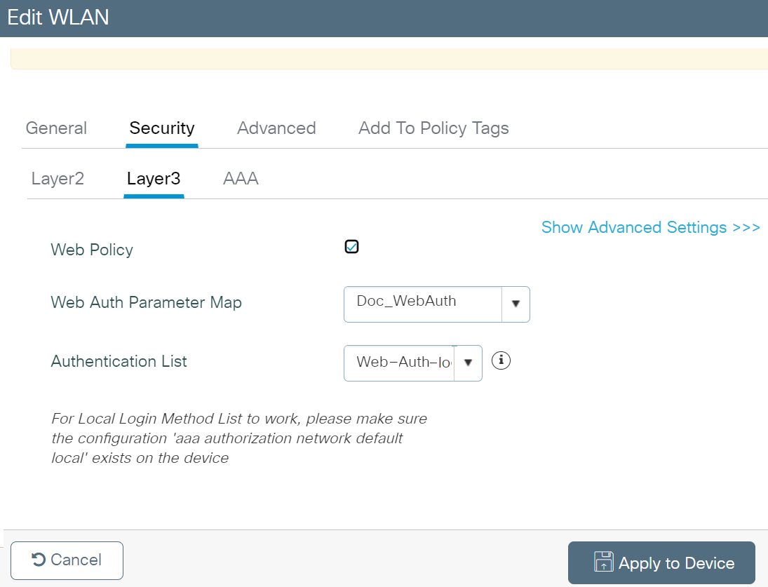
- Click the AAA tab.
- From the Authentication List drop-down list, select the dot1x Authentication Method List created in the Creating a dot1x Type AAA Method List section.
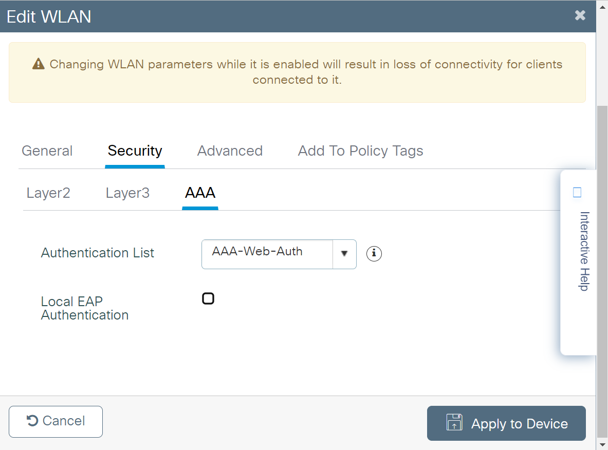
- Click Apply to Device.
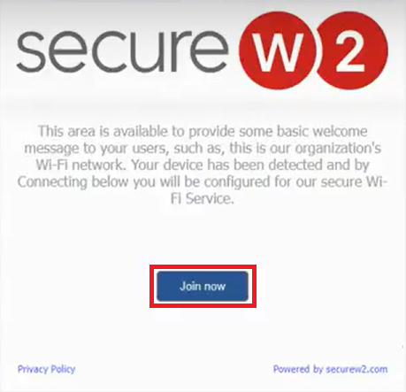
- Connect to the open guest network.
- Click Join now.
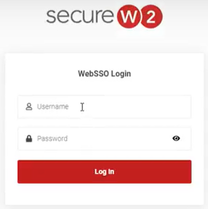
- On the Landing Page, enter the user credentials required to log in. You will be directed to an SSO page if the Identity Store is a third-party Identity Provider.
- Upon successful authentication, users will be redirected to the configured URL/website.